DevOps

Top Remote Access Software (Remote Desktop Software) 2021
{loadposition top-ads-automation-testing-tools} Remote administration tools help IT professionals to debug...
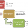
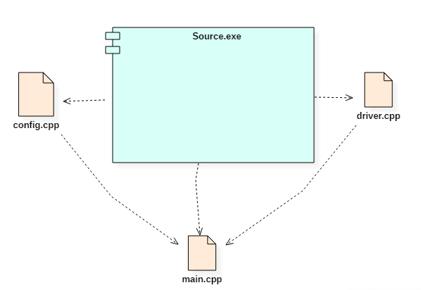
When modeling large object-oriented systems, it is necessary to break down the system into manageable subsystems. UML component diagrams are used for modeling large systems into smaller subsystems which can be easily managed.
A component is a replaceable and executable piece of a system whose implementation details are hidden. A component provides the set of interfaces that a component realizes or implements. Components also require interfaces to carry out a function.
UML Component diagrams are used to represent different components of a system.
In this UML tutorial, you will learn:
A component is a replaceable and executable piece of a system whose implementation details are hidden. A component provides the set of interfaces that a component realizes or implements. Components also require interfaces to carry out a function.
It is a modular part of a system that encapsulates its contents. They are the logical elements of a system that plays an essential role during the execution of a system.
A component is similar to a black box whose external behavior is defined by a provided interface and required interfaces.
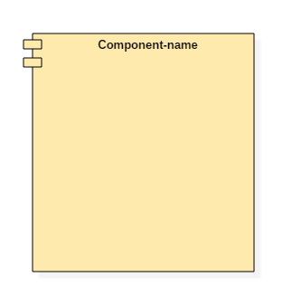
A component is represented with classifier rectangle stereotypes as
<< component >>. Component details are hidden for the outside world. The name of a component is placed at the center of a rectangle. A component icon is displayed at the upper right corner of a rectangle, which is optional.
A component in UML is represented as follows, 
The interface is a named set of public features. It separates the specification of functionality from its implementation by a class diagram or a subsystem. An interface symbol cannot be instantiated. It declares a contract that may be realized by zero or more classifiers such as a class or a subsystem.
Anything that realizes an interface accepts the functionalities of the interface and agrees to abide by the contract defined by the interface.
If the implementation language does not support interfaces the use abstract classes, interfaces are named just like classes, in UpperCamelCase.
There are two types of interfaces,
We can connect provided and required interfaces using assembly connector.
Advantages:
Disadvantages:
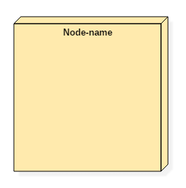
It is a component base that acts as a decomposition unit for larger systems. It is a logical construct which is used to break down an extensive system into smaller systems which are known as subsystems. This process makes it easy to manage each subsystem efficiently.
A subsystem cannot be instantiated during runtime, but their contents can be initialized. When subsystems are connected, it creates a single system.
A port is an interaction point between a classifier and an external environment. It groups semantically cohesive set of provided and required interfaces. A port can be used in UML without specifying the name of the port. A port may have visibility. When a port is drawn over the boundary of a classifier, then it means that the port is public. It also means that all the interfaces used are made as public.
When a port is drawn inside the classifier, then it is either protected or private.
A port also has multiplicity that indicates the number of instances of the port classifier will have. A port in UML diagram is denoted as given below, 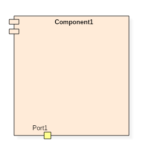
Here the port1 is drawn over the boundary, which means it has visibility as public.
UML component diagrams have significant importance. Component diagram variously differs from other diagrams. While other diagrams are used to represent the system, working of a system or the architecture of a system. Component diagrams are used to describe the working and behavior of various components of a system.
It represents how each component acts during the execution of a system.
These are the static diagrams of the unified modeling language. A component diagram is used to represent the structure and organization of components during any instance of time.
Component diagrams are used for modeling the subsystems. These subsystems collectively represent the entire working view of any system. A single component cannot visualize the whole system, but the collection of multiple components can.
So, component diagrams are used for,
Component diagrams are different from any other diagrams in UML. Component diagrams are used to display various components of a software system as well as subsystems of a single system. They are used to represent physical things or components of a system. It generally visualizes the structure and an organization of a system.
It describes how various components together make a single, fully functional system. We can display each component individually or collectively as a single unit.
A component is nothing but an executable piece of a system. Various components together make a single system. Component diagrams are used widely during the execution phase of any system.
Before modeling the component diagram, one must know all the components within the system. The working of each component should be mentioned. Component diagrams are used to analyze the execution of a system.
One should also explore each component in depth to understand the connection of a component to other physical artifacts in the system.
The relationship amongst various artifacts, libraries, and files are the essential things required during modeling of a component diagram.
{loadposition top-ads-automation-testing-tools} Remote administration tools help IT professionals to debug...
What is Perl? PERL is a high-level, general-purpose, interpreted, dynamic programming language. Perl...
What is Greedy Strategy? Greedy algorithms are like dynamic programming algorithms that are often...
Monitoring the temperature of the processor is essential because it can affect the performance of...
Duplicate file finders are tools that help you to find and remove repeating files in folders and...
Slideshow maker software are applications used to develop presentations or videos with different...