Blog

10 BEST CPU Temperature Monitors Software (2021 Update)
Monitoring the temperature of the processor is essential because it can affect the performance of...
In this UML Notation Cheat Sheet, you will learn:
A thing can be described as any real-world entity or an object. Things are divided into various categories in UML as follows,
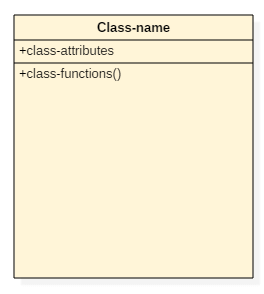
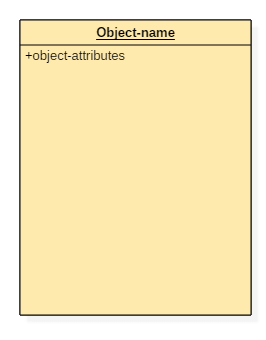
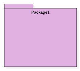
Structural things are all about the physical part of a system. It is the noun of a UML model, such as a class, object, interface, collaboration, use case, component, and a node.

They are the verbs of a UML model, such as interactions, activities and state machines. Behavioral things are used to represent the behavior of a system.
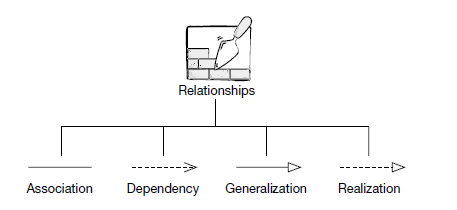
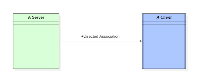
The relationship allows you to show on a model how two or more things relate to each other.


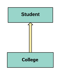
Generalization relationship :- It is also called as a parent-child relationship.This type of relationship is used to represent the inheritance concept.

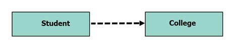
Realization relationship :- Realization relationship is widely used while denoting interfaces.
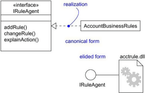
Realization can be represented in two ways:
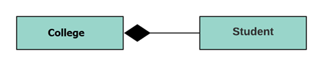
Composition :- Composite aggregation is described as a binary association decorated with a filled black diamond at the aggregate (whole) end.It is not a standard UML relationship, but it is still used in various applications.
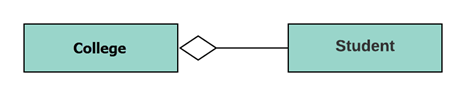
Aggregation :- aggregation relationship, the dependent object remains in the scope of a relationship even when the source object is destroyed.An aggregation is a subtype of an association relationship in UML.
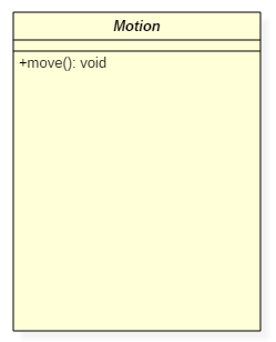
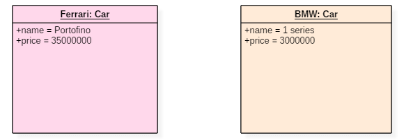
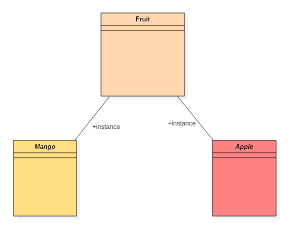
It is a class with an operation prototype, but not the implementation.In UML The only difference between a class and an abstract class is that the class name is strictly written in an italic font.
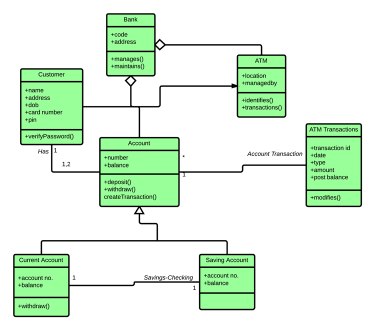
ATMs system is very simple as customers need to press some buttons to receive cash. However, there are multiple security layers that any ATM system needs to pass. This helps to prevent fraud and provide cash or need details to banking customers.
Use Case Diagram captures the system's functionality and requirements by using actors and use cases. Use Cases model the services, tasks, function that a system needs to perform.
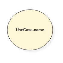
Use-case :- Use-cases are one of the core concepts of object-oriented modeling. They are used to represent high-level functionalities and how the user will handle the system.
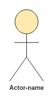
Actor :- The actor is an entity that interacts with the system. A user is the best example of an actor.
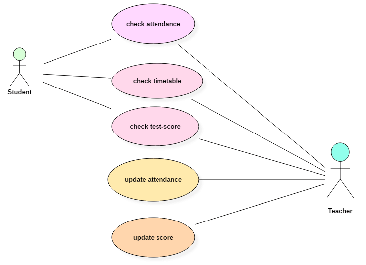
In the below use case diagram, there are two actors named student and a teacher. There are a total of five use cases that represent the specific functionality of a student management system. Each actor interacts with a particular use case.

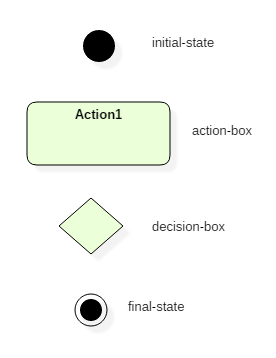
State machine:- It used to describe various states of a single component throughout the software development life cycle.
Their are 4 type of state in state machine :-
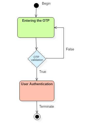
Example of State Machine Diagrams :- There are a total of two states, and the first state indicates that the OTP has to be entered first. After that, OTP is checked in the decision box, if it is correct, then only state transition will occur, and the user will be validated. If OTP is incorrect, then the transition will not take place, and it will again go back to the beginning state until the user enters the correct OTP.
Activity diagram :- activity diagram is used to represent various activities carried out by different components of a system.
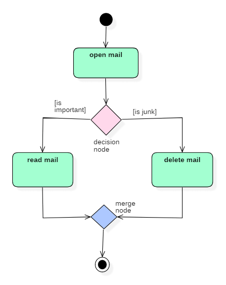
Example of Activity Diagram :-Following diagram represents activity for processing e-mails.
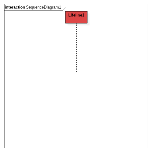
The purpose of a sequence diagram in UML is to visualize the sequence of a message flow in the system.A sequence diagram is used to capture the behavior of any scenario.

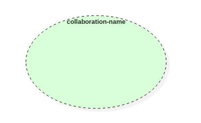
Collaboration :- It is represented by a dotted ellipse with a name written inside it
Example of Collaboration diagram :-

A timing diagram specifies how the object changes its state by using a waveform or a graph. It is used to denote the transformation of an object from one form into another form.
Example of Timing diagram :-

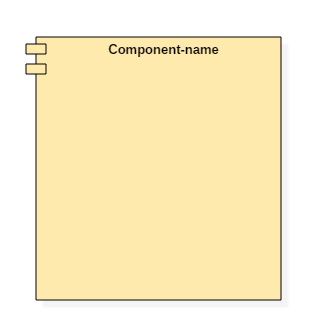
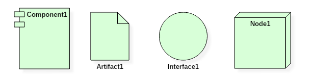
Component :- A component notation is used to represent a part of the system.
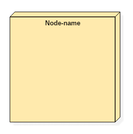
Node :- A node can be used to represent a network, server, routers, etc. Its notation is given below.

Structure of a component :- A component is represented with classifier rectangle stereotypes as<< component >>.
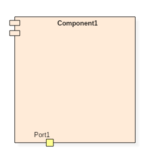
Port :- A port is an interaction point between a classifier and an external environment. It groups semantically cohesive set of provided and required interfaces.
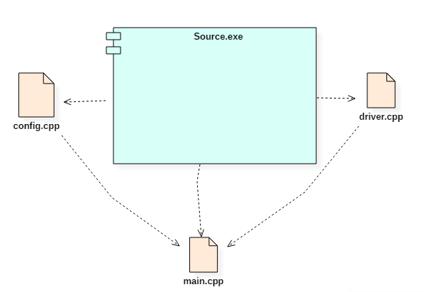
Example of Component diagram :-
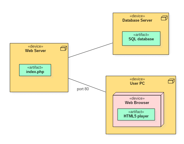
Deployment diagram :- A deployment diagram represents the physical view of a system.
A deployment diagram consists of the following notations:
Example of a deployment diagram :- Following deployment diagram represents the working of HTML5 video player in the browser.
Monitoring the temperature of the processor is essential because it can affect the performance of...
Software engineering is defined as a process of analyzing user requirements and then designing,...
Here are Kubernetes Interview Questions for fresher as well as experienced candidates to get the...
What is Statistical Inference? Stastitical inference is the art of generating conclusions about...
EPUB file reader is a file viewer software that allows you to view the ebooks stored in EPUB...
Video quality enhancers are tools that enable you to improve the resolution of a video. These...